The Fiber Distributed Data Interface (FDDI) is a set of standards that can be used to create a computer network that has a high bandwith and good performance. FDDI can be used to create a network that spans up to 200 kilometers and has a bandwidth of 100 Megabits/second (Mbits/s) [1] A network is a collection of hardware and software components that allows a number of computers to send data between themselves [2]. The actions that are performed in transferring data between computers can be divided into several different parts.
Back to TopFirst, the data must originate from somewhere. Usually the data comes from an end user that is interacting with an application. When the user gives a command to send a piece of information somewhere, the application passes the information, as a stream of bits, to another program along with a destination where the information should go. That program then compresses and encodes the information so that the resulting bit stream is relatively short and contains enough redundancy for error checking to be possible once the information is received. That stream of bits is then turned into a signal that can be transmitted over the channel, and the signal is transmitted to the appropriate destination.
The process is reversed when the signal is received. The signal is converted to a set of bits which are then decoded, uncompressed, and passed to an end user at the receiving end. There is also some error checking, and possibly data recovery, done to see if the signal was transferred successfully.
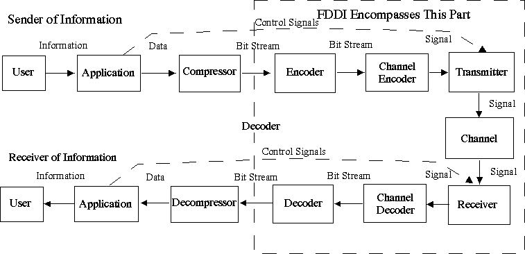
FDDI is concerned only with the parts of the transmission processes that are the furthest away from the end user. FDDI only deals with taking a bit stream, encoding it, transferring it, and then decoding it. Figure 1 illustrates all the parts of this process.

Figure 1: Data Flow Diagram
The view that is shown in figure 1 deals mainly with the flow of data. This entire, process, however, is not automatic, and there is a large amount of control that has to be performed for the data to be transmitted successfully.
Back to TopA model that is commonly used when discussing how the process is divided is called the Open System Interconnection (OSI). OSI is an International Standards Organization (ISO) standard that defines seven layers that perform different tasks to move data over a network. [3]
The following is a list of the layers from that standard:
FDDI deals only with the last two layers of the OSI model. These two layers are the data link layer and the physical layer. [4] The physical layer is responsible for transferring the actual bits over the physical media (e.g. cable) from one point to another point, while the data link layer ensures that two computers can use the network to send data as a sequence of bits between each other [3].
FDDI has been standardized to facilitate its use when creating networks. The orignal FDDI standard was defined in ANSI X3T9.5 and in ISO 9314. [4] This standard has been around since 1989, and a new standard was released since then. The new FDDI standard was defined in ANSI X3T12 [5].
The elements that comprise the FDDI standard, are called physical medium dependent layer (PMD), physical layer protocol (PHY), media access control (MAC), and station management (SMT). PMD and PHY are part of the physical layer, MAC is part of the data link layer, and SMT oversees the activities of the other three elements. FDDI does not implement a logical link layer. Instead it uses a standardized logic link layer protocol that is used by other standards as well. [4] Table 1 shows how FDDI fits into the OSI model.
| OSI Model | FDDI Standard | |||
| Layer | Name | Subdivision | Element | |
| 2 | Data Link | Logical Link Layer | (standard protocol) | |
| Medium Access Control | MAC | SMT | ||
| 1 | Physical | PHY | ||
| PMD | ||||
Table 1: FDDI as seen using the OSI model[4]
PMD specifies the quality and type of the actual hardware that has to be used. The hardware includes cables, connectors, transmitters, receivers, and optical bypass switches.
PHY deals with sending and recovering data over the physical medium. PHY encompasses encoding, decoding, data conversion, and clock recovery. This layer is concerned with how the computers are connected together to form a network topology.
MAC is responsible for converting the data to a form that can be sent over the network and for ensuring that the data is being sent to the right address. The conversion of the data involves cutting the data into sections (also called frames) and then adding error detection and recovery information.
SMT is used to manage, control, and monitor everything that is happening with the other three elements. It also responds to requests for information regarding traffic statistics. [4]
FDDI does not have a logic link layer protocol because it uses the IEEE 802.3 LLC protocol. This protocol is also used by other network standards such as Ethernet and Token Ring. The fact that all of these different standards use the same protocol allows everything that is considered above the second layer of the OSI model to use all of these different standards without caring which one is actually used to transmit the data. [5]
Back to TopWith respect to figure 1, PMD encompasses the channel encoder, transmitter, the channel itself, the receiver, and the channel decoder.
PMD defines the hardware that is used, the way the signal is transmitted over the network, and the topology of the network. There are several different standards that can be used for the hardware, but there is only one topology that dictates how the hardware is connected. The standards that can define the specifications for the hardware that can be used for the PMD layer include the Fiber PMD standard, the Twisted Pair PMD (TP-PMD), the Single Mode Fiber-PMD (SMF-PMD), and the Low Cost Fiber-PMD (LCF-PMD). [6]
The different PMD specifications have different requirements for the hardware. The Fiber PMD is defined by the ANSI X3T9.5/48-48 standard. The standards that deal with fiber optic cables define nominal values for various properites including the wavelength of light and the size of the aperture used in transmitting the signals. The different standards also define different lengths for the cables that can be used to connect two nodes in the network together. [6] The standard that deals with copper wire (TP-PMD) on the other hand deals with the characteristics of the wire and the geometry of the various connectors. TP-PMD is part of the newer FDDI standard and is defined in ANSI X3T12. [7]
PMD not only specifies a medium to transmit signals, but also the shape of the signals. The old ANSI X3T9.5 standard requires that the signal is transitted as a non return to zero invert on one (NRZI) signal. [8] An NRZI code goes between -1 and 1 if the input bit is a 1, and it stays the same if the input bit is a 0. So for example, if the output signal starts at -1, and the input is 01011001, then the output would be -1,1,1,-1,1,1,1,-1, because the rules for the output are:
The TP-PMD standard under ANSI X3T12 on the other hand, uses a level 3 multi-level transition (MLT-3) encoding. [7] MLT-3 encoding has transitions at the same points as NRZI, but the transitions go up and down in a cycle from -1 to 0 to 1 to 0 to -1, etc. So in the example above the output would be -1,0,0,1,0,0,0,-1, because the rules for the output are:
In reality, signals transmitted over an FDDI network go between -7 and 7 Volts. So in the previous examples, the outputs would be -7 Volts, 0 Volts, and 7 Volts, instead of -1,0, and 1, respectively. [11]
These two channel encodings ensure that the signal changes as long as the input bit stream has frequent occurences of 1's. The encoder that is implemented as part of the physical layer protocol must therefore ensure that a 1 frequenty appears in the bit stream.
Back to TopThe physical layer protocol defines both how the initial signal to be sent is encoded as well as the physical topology of the network. One of the major limitations of FDDI is that there can be at most 500 stations connected together in the network.[12]
Back to TopThe data is encoded using the 4B/5B rule. The data is split into groups of 4 bits. Each group of data is then turned into 5 bits, such that there are no more than two successive zeros that can occur in the 5 bits. This is to ensure that the signal that is sent to another station will change at least once in 5 bits (since a 1 requires a change under NRZI channel encoding). Frequent occurences of 1 are a good thing because they cause the signal to vary. A signal that does not vary often causes synchronization problems. Any set of 5 bits that is not used by all the different possible 4 bit data groups can be used as a control signal.[8]
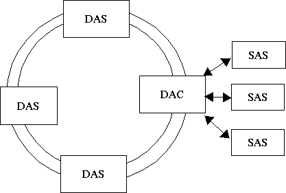
Back to TopThe FDDI network can be seen as a double ring that can contain many main nodes, which break the ring whenever they connect to it. The double ring can be seen as a primary ring and as a secondary ring. The data travels in opposite directions on each ring. The main nodes are either called Dual Attach Stations (DAS) or Dual Attach Concentrators (DAC). Both must take in the inputs of both rings, and then output either their own data or whatever was passed to them.
The two main nodes have to perform a lot of work in terms of passing the signals across the channel. The hardware requirements for these nodes are therefore very high and go beyond the capabilities of most computer. It is therefore impossible to connect regular computers to the main ring.
A solution to this limitation is to connect regular computers as Single Attach Stations (SAS's) to a DAC. Since the SAS's do not have to worry about keeping the data flow in the main ring going, the hardware requirements are not high. This solution is the reason why there are two different types of main nodes. The DAC can have multiple SAS's attached to it, while a DAS has none. Figure 2 illustrates a FDDI ring. [13]

Figure 2: A typical FDDI topolgy
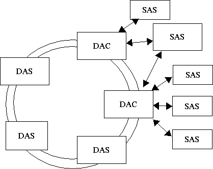
It is also possible to have a SAS connected to two DACs. This is used as a fault tolerance measure that allows for a critical SAS to stay active even if something goes wrong on the network. Figure 3 illustrates how an SAS can be connected to multiple DACs. [11]

Figure 3: An example of a SAS with extra fault tolerance.
Back to TopMAC deals with controlling the flow of information. This layer defines the ways that data and control signals are divided up into frames, ensures that the frames go to the right places, and checks the received frames for errors. [13]
The data is put into a data frame that contains:
The Frame Check Sequence is a set of bits that is used to check for errors in the transmission. FCS is based on a Cyclic Redundancy Check (CRC) algorithm. [14]
The CRC algorithm works as follows:
The receiver can check if an error occurred by dividing the received appended number, and dividing that by the predefined number. If the remainder is 0, then no error is detected. If the remainder is not 0, then an error occurred. [15]
The token has a frame with the following four items:
Data is passed around the ring through a protocol called token passing. There is a special piece of data called a token. At any given moment int time, only one computer can hold onto this token, and only the computer that has this token can use the network to transmit data. This process ensures that only one piece of data is sent over the network.
A computer only holds onto the token when it needs to send some data. Otherwise, the token is passed around in a circle until a computer wants to transmit something. When a computer wants to transmit data, it keeps the token, and then sends the data over the network. Each computer (node) in the network passes that data onto the next computer. When the data reaches its destination, the data is duplicated by that computer. Once the data is sent all the way around the ring, the computer that sent the data sees that its data has been sent properly and lets go of the token. [1]
Back to TopStation Management (SMT) is used to keep track of what is happening, and also to fix any errors. SMT was designed so that an FDDI network would not need any extra equipment to monitor, manage, and fix the network. If SMT detects errors it can remove the station from the network. The network can handle such disruptions because it has been designed with this in mind. [11]
SMT is also responsible for all of the configuration that takes place when a network is started up. During initial configuration, SMT must ensure that all of the connections on the network are properly working, and that each node in the network has information that allows it to send information to the proper destinations. SMT must also ensure that all of the addresses on the network are unique.
On top of that, SMT must continuously monitor what is happening to keep statistics and to properly manage all of the components of the network. [16]
Back to TopThe Fiber Distributed Data Interface is a standard that can be used to create fast networks that can span long distances. This standard defines the way in which data is encoded and sent over a network. It also uses the same standard protocols as other network technologies such as Ethernet and TokenRing, and can therefore be used in a wide variety of cases.
Back to Top[2] local-area network - Webopedia Definition and Links
[3] OSI - Webopedia Definition and Links
[4] Fiber Distributed Data Interface
[5] SysKonnect Technology - FDDI - Facts and Knowledge
[6] SysKonnect Technology - FDDI - Facts and Knowledge
[7] SysKonnect Technology - FDDI - Facts and Knowledge
[8] PVM: Physical Interface, QUB
[9] Optimized Engineering Corporation - NRZI
[10] Optimized Engineering Corporation - MLT-3
[11] FDDI
[12] SysKonnect Technology - FDDI - Facts and Knowledge
[13] PVM: Network Configureation, QUB
[14] Telecommunications Dictionary
[15] How the CRC algorithm works
[16] SysKonnect Technology - FDDI - Facts and Knowledge
Back to Top
This web page is maintained by Borys
Bradel. Last update: Nov. 19, 2001
Address: http://www.eecg.utoronto.ca/~bradel/projects/fddi/index.html